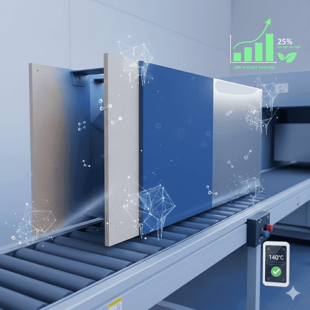

UV-curable powder coating separates two events that occur together in a conventional thermoset powder oven: the powder first receives enough heat to melt and flow, then ultraviolet energy activates photoinitiators and cures the film. That separation can reduce the substrate's thermal exposure and make selected heat-sensitive parts practical candidates. It does not mean the process is heat-free, instant for every geometry or automatically less expensive.
This guide helps manufacturers, finishers and buyers decide whether UV powder deserves a line trial and how to qualify it without relying on generic cure seconds, energy-saving percentages or payback claims.
Understand the two-stage process
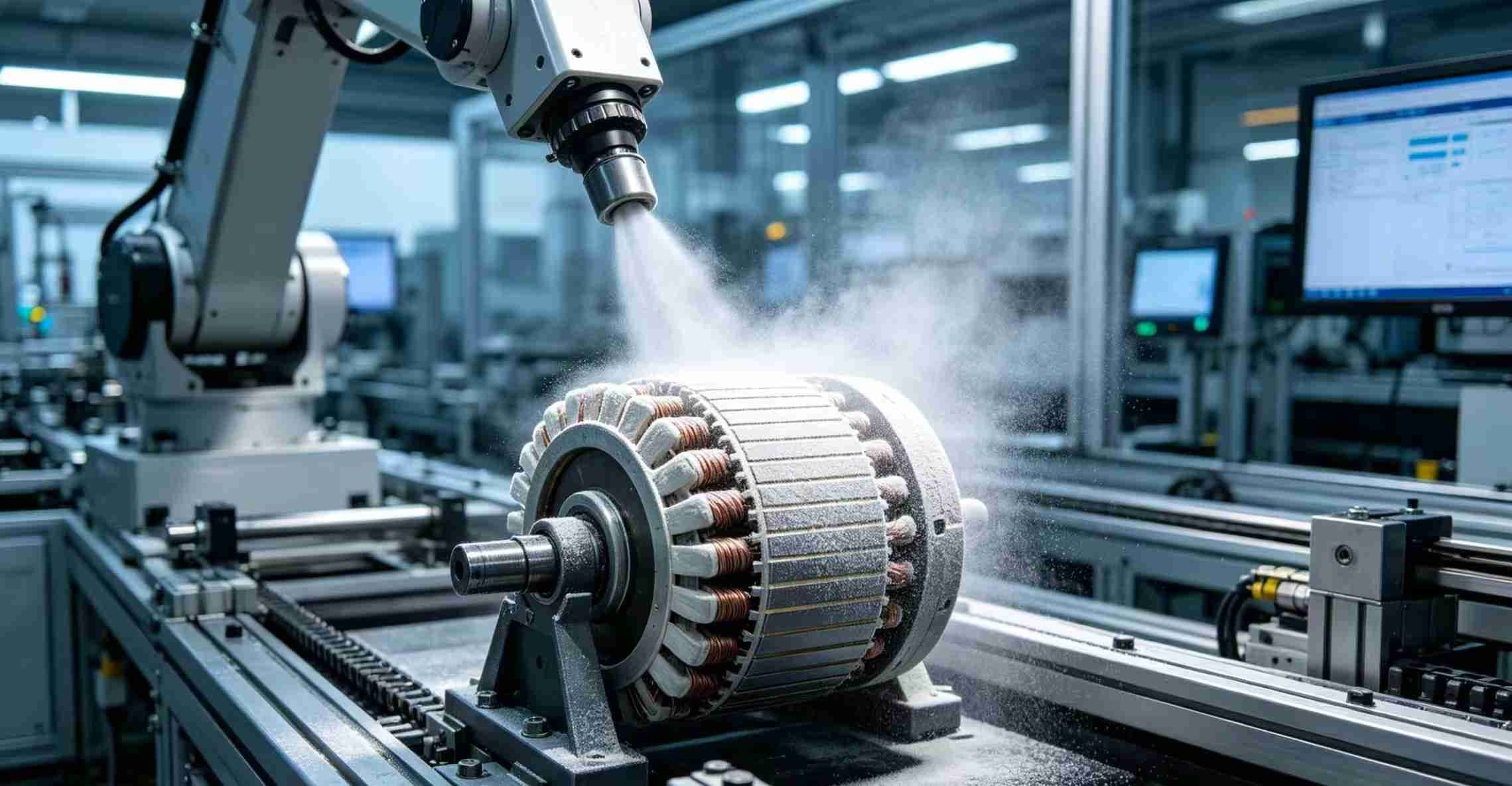
A UV powder line still needs controlled electrostatic application, a melt/flow stage, UV exposure and cooling. The first stage must heat the deposited powder sufficiently to form a continuous film. The second must deliver the wavelength, irradiance and energy required by the formulation at every relevant surface.
RadTech papers describe this decoupling of melt/flow from cure, and Covestro describes UV-curable powder binders designed for low-temperature, short-cycle processing on heat-sensitive substrates. Their published times and temperatures belong to their systems and demonstrations. They are useful evidence of the technology, not universal settings for DAMEI or another formulation.
Screen the substrate before selecting a powder
Common development targets include MDF, engineered wood, some solid wood, plastics, composites and preassembled parts containing seals, electronics or lubricants. Each introduces different constraints. MDF moisture and conductivity vary; wood can outgas and move; plastics can distort, carry mold release or charge poorly; assemblies can create shadowed UV areas and incompatible materials.
Record substrate grade, density or alloy, moisture/conditioning, machining, fillers, adhesives, contaminants, maximum thermal exposure and dimensional tolerances. For plastics, identify resin, additives and any conductive primer. A supplier should not recommend a production cycle from the words “MDF” or “ABS” alone.
Define why UV powder is being considered
A credible project has a measurable reason: reduce thermal exposure, coat an assembled component, shorten occupied line length, achieve a powder finish on MDF, avoid a solvent-borne process or increase throughput within a known bottleneck. Define the current baseline before calculating benefit.
Capture actual energy use, warm-up, changeover, rejects, line density, labor, maintenance, floor space and required output. Then compare the proposed UV line on the same part mix and quality level. Published case economics are not a substitute for the buyer's utility tariff, utilization and capital quote.
Match formulation, color and film build to UV transmission
UV energy must reach enough of the reactive film to achieve the specified cure. Pigments, fillers, metallic effects, opacity and excessive thickness can change penetration. Dark or highly filled formulations may require a different photoinitiator package, lamp spectrum or process window. A clear or light laboratory panel does not establish performance for every color.
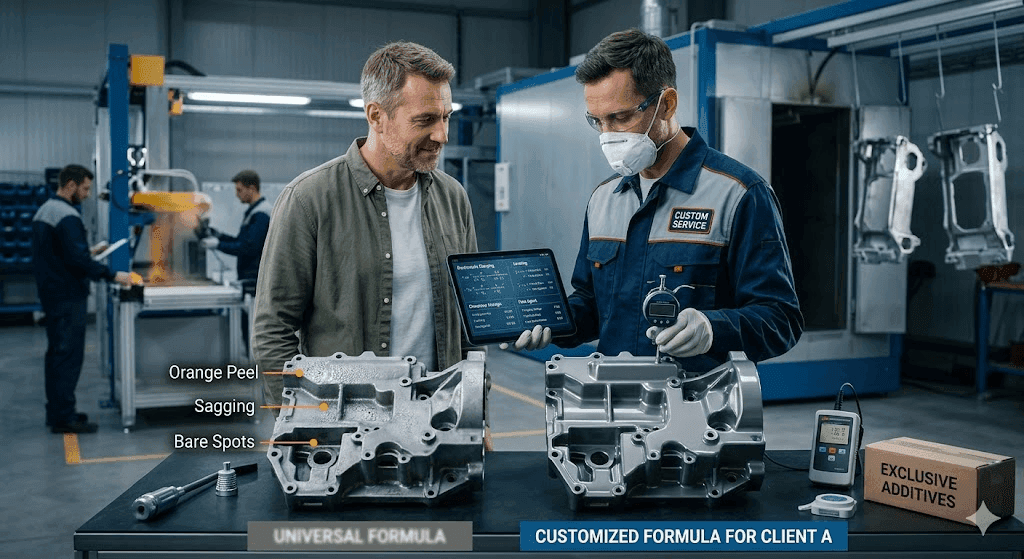
Define color, gloss, texture, opacity, film-thickness range and appearance tolerance at the start. Review each formulation separately and retain its exact revision. The film-thickness guide explains why too little and too much film can create different failure modes.
Engineer the melt and flow stage
The substrate and powder must reach a state where the film levels and air can escape without damaging the part. Control heater type, distance, zoning, conveyor speed, part loading and actual substrate temperature. Infrared response can vary with color, moisture and geometry. Air temperature or emitter setting alone is not a cure record.
Use representative thermocouples or another validated method at the fastest and slowest heating locations. Examine edges, routed MDF features, recesses and joints for incomplete flow or outgassing. Compare the profile with the exact formulation data sheet. Our cure-schedule guide provides a framework for recording part temperature rather than relying on equipment settings.
Specify UV delivery with measurable parameters
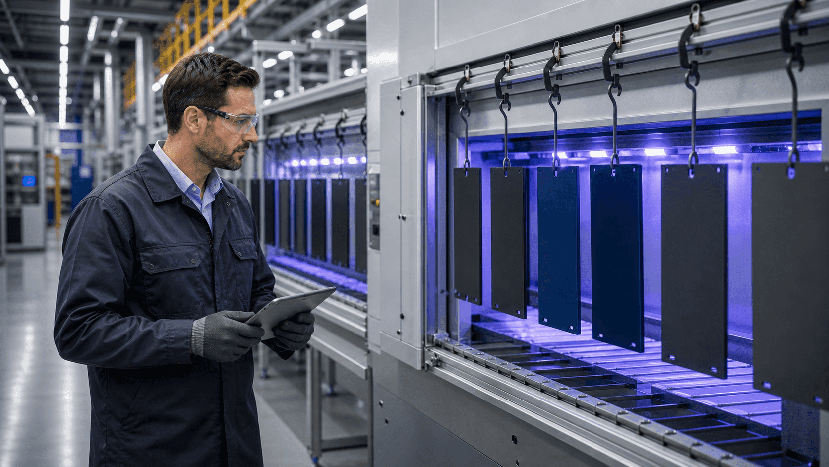
“Expose for ten seconds” is incomplete. The same time can deliver different energy when lamp type, spectrum, power, distance, reflector condition, conveyor speed or angle changes. Define the formulation's required spectral response and measure UV irradiance and dose with equipment suited to the lamp system. Establish radiometer checks, lamp aging limits, reflector cleaning and replacement rules.
Mercury, microwave-powered and LED sources have different spectra and operating behavior. A formulation developed for one source is not automatically qualified on another. Confirm the lamp/formulation pairing with the powder and equipment suppliers. Record all line settings and measurement-device identity in the approved process.
Design around line-of-sight and shadowing
UV energy travels primarily by line of sight. Deep recesses, back faces, overlaps, holes and assembled hardware can receive less exposure even when the visible face is cured. Part rotation, multiple lamp banks, robotic motion or reflectors may improve access, but the finished geometry must be mapped and tested.
Mark worst-case surfaces on the drawing. Use radiometry where possible and film tests at each critical location. If a required surface cannot receive enough UV, consider redesign, a dual-cure formulation or a different coating process rather than accepting an unverified shadow zone.
Prove cure with more than surface feel
A film can feel hard while deeper or shadowed regions remain undercured. Define the test set appropriate to the part: solvent resistance, hardness, adhesion, impact, abrasion, chemical exposure, appearance or spectroscopic/thermal methods where justified. Each method needs a specimen, conditioning period, procedure and acceptance value.
Do not use one pencil-hardness or solvent-rub result as universal cure proof. Correlate fast line checks with fuller qualification evidence. The quality-control test guide helps keep hardness, adhesion, cure and durability claims separate.
Qualify adhesion and surface preparation
Heat-sensitive does not mean preparation-insensitive. Dust, sanding residue, moisture, release agents, weak fibers or primers can control adhesion. Define cleaning, sanding or sealing, conductive treatment if used, handling time and rework rules. Use production material and normal machining, not only specially selected coupons.
Run the specified adhesion test after the required conditioning and exposures. Record the failure mode: coating separation, substrate tear, cohesive film failure and adhesive failure do not mean the same thing.
Run a staged line qualification
A practical sequence is:
- laboratory screening of substrate, color and basic cure response;
- pilot application to map deposition, melt, flow and UV access;
- design-of-experiments around the proposed process window;
- performance testing on representative parts;
- extended run including starts, stops, changeovers and normal variation;
- capability review at critical locations;
- approved sample, settings and control plan;
- production monitoring and defined requalification triggers.
Include worst-case moisture, thickness, color, geometry and line loading. A short demonstration on one flat panel is not enough for capital approval.
Build a realistic cost and capacity model
Request separate quotations for powder, application equipment, preheat/melt zone, UV source, shielding, ventilation, radiometry, controls, maintenance and training. Compare floor space and throughput using the real product mix. Include lamp or LED-module life, reflector cleaning, color changes, rejected parts, warm-up and planned downtime.
Calculate benefit as a range under conservative utilization assumptions. Do not publish a percentage saving or investment recovery time until measured production data and the installed quote support it. Where throughput is the goal, confirm that coating is the true bottleneck and that upstream and downstream operations can accept the rate.
What to include in a UV powder RFQ
Provide substrate specification, moisture/conditioning, part drawings, thermal limit, grounding or conductive-treatment approach, color and finish, film range, line concept, available heater and UV source, critical shadow areas, required tests, current baseline, annual volume and approval stages. Identify whether the project is a material replacement, new line or retrofit.
DAMEI can review whether a UV-curable or low-temperature thermal powder is the better starting point and prepare a development sample where capability is available. Final suitability requires a documented line trial. Use the custom powder specification guide and contact DAMEI with the complete part and process brief.
Frequently asked questions
Is UV-curable powder coating a no-heat process?
No. The powder must first receive enough heat to melt and flow. UV energy then drives the main cure reaction.
Can every UV powder run under UV LED lamps?
No. Lamp spectrum and formulation photoinitiators must be matched and validated.
Is UV powder suitable for any plastic or MDF?
No. Substrate grade, moisture, conductivity, outgassing, geometry and thermal response all require testing.
Does a shorter cure stage prove lower cost?
No. Installed capital, utilization, line balance, maintenance, rejects and local energy prices determine economics.